

Finally, a few months after obtaining them, I’ve been able to start digging into these ancient arcade boards I’ve obtained. I started with the Allied Leisure “Paddle Battle” board, since, as a pong clone, I figured it would be a simple one to start with, and that assumption more or less seems to have been correct.
First off – this board is labeled “Paddle Battle” correct? Therefore, it stands to reason that I should go off the Paddle Battle schematics, right? Well, funny thing about that – it seems Allied Leisure had the “Paddle Battle” moniker on both the actual Paddle Battle game as well as the four player variant with the name of Tennis Tourney! It took me a while to catch on to this fact, namely because WHO WOULD PUT THE SAME NAME ON TWO DIFFERENT BOARDS, but also, according to the schematic for Paddle Battle, the card edge pinout didn’t match with what I had on my board. My first thought was that I just had a different board revision. Luckily, I was still able to suss out where the video signal was, and the power and ground connections were pretty obvious, and I continued to operate for some time that I was working on a Paddle Battle board.
The game worked immediately upon sending it 9V of power! Or at least, it seemed like it was doing what is supposed to somewhere in there?
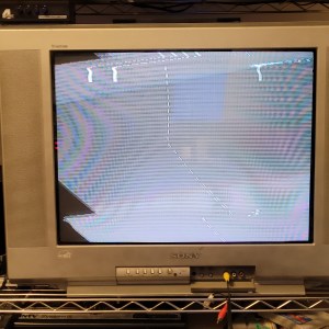
Getting a decent picture proved to be a challenge. You see, older televisions tend to be very forgiving with the signals they receive. After all, these old cathode ray tube workhorses had to be able to pick out useable, high-bandwidth signals literally out of the air with all the other radio frequency noise surrounding them, so they tend to be very tune-able. You can adjust not only brightness and contrast, but also vertical and (sometimes) horizontal hold, and fine frequency tuning. You see, these very early video game boards didn’t need a spot-on perfect signal for the television inside the cabinet to pick it up. So much was available to the end user to fine tune the picture that it really wasn’t necessary.
HOWEVER – say you’re somebody like me who’d like to be able to send the video to a capture card so we can get archival footage of the game running? Capture devices and upscalers like the RetroTink or what have you tend to be a little pickier with the signal that’s coming into them which sometimes can be adjusted to a certain degree. The signal coming off of this Paddle Battle board, however, is so out of whack that my circa 2003 Trinitron couldn’t properly pick it up. It quickly became clear that if I was going to be able to put this into an upscaler for direct capture, the video signal had to be massaged through hardware.
My first thought on this was to try to apply some sort of amplifier circuit, as that is often what is done on older, RF-only consoles, thinking that perhaps the same sort of logic would apply. It didn’t work the way I was expecting it to, and perhaps if I had paid attention to the giant electrolytic cap the signal was running through, I’d notice that it was doing plenty of amplifying on its own. But I powered through, tinkering with an amplifier circuit, trying various voltage division in order for my poor CRT to make sense of the signal. Ultimately, the solution was twofold – one is that I removed the resistors combining the separate signals (paddle, ball, score) and replaced them with pontentiometers, so that an optimal signal balance could be achieved between the separate components. Second? A 75 ohm resistor between the RCA jack’s ground lug and ground. That was it. No amplification needed.
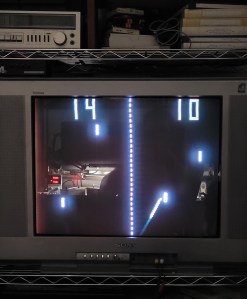
All it needed was a harness and a box with controls in it, and voila! The game is now playable and is ready for some direct capture footage. I also now hope to take a high-quality reference photo of the board, as well as for the other games I intend to document. Next up is a big one, and one that will probably take a while to get up and running given the materials I currently have on hand.

