
If you remember the last time I wrote about this, after much wrestling and tinkering I finally got the main video circuit working! Mistakes were made both on my end and the original schematics I was working off of, but I was able to overcome these things with raw determination in spite of my relative inexperience with such relatively complicated designs.
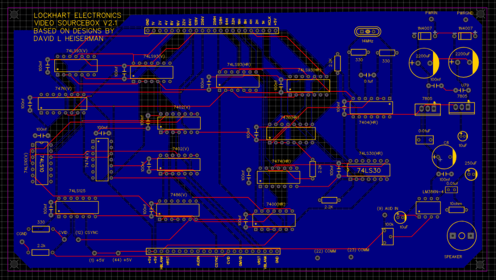
I wasn’t satisfied with how everything was implemented in my layout, however. First of all, having the horizontal, vertical, and input elements all on separate boards was very unwieldy. Second, though my mishaps I learned two very important, basic lessons in electronics in general: ground planes are VERY important in PCB design, and decoupling capacitors are a great idea. Both of these things help to achieve the same goal: removing noise from signals. I really underestimated how many issues signal noise can cause. So I went back to work in EasyEDA, this time putting everything on a single board, adding the much needed decoupling capacitors, and adding in a sound amplifier circuit for use in future projects. These new boards were built and tested without a hitch.
Now that the video board had been figured out, it was time to make the next big step; getting something user controlled on the screen. The book doesn’t explore implementation of actual game mechanics until chapter 5, with chapters 3 and 4 dedicating themselves to pattern generation and static figure creation. Interesting in its own right for sure, but after doing all that work getting the video generation to work at all, I was ready to skip all that and just get right into things. Most of the game builds featured in the book don’t really use the more complicated graphics generation examples.
A perfect project to, ahem, get things moving is generating a simple white dot that can be controlled across the screen vertically and horizontally. It’s a pretty uncomplicated circuit, and easy one to do up on the breadboard. The heart of it is a 556 timer, which, with the help of a 500k potentiometer can “shorten” the horizontal and/or vertical reset pulses, creating a little square to move around. I still don’t completely understand everything going on in these circuits, but these hands-on experiences are definitely teaching me a lot about digital logic circuits and timers. After about an hour or so, I got this:
Success! Now it was time to double up the circuit, and create a simple game of tag, outlined just a few pages later. Since it was the first actual game using the video board, I thought it more appropriate to give it a more permanent installation through the creation of a PCB. As of my typing this, I’ve since learned A LOT more about the software I’m using (EasyEDA), and looking at the design I did just makes me shake my head, realizing how much easier I could have made things for myself.
It was quick to put together, due to the relatively few components necessary, but I didn’t get anything on the first power on. I’ve kinda started to get used to this scenario, and I’m learning to take it not as some sort of display of ineptitude on my part, but just a normal part of the process. First off, I missed a VCC connection. A bodge fixed that pretty quickly. The other one required a bit my sleuthing, but didn’t take nearly as long to troubleshoot as the sourceboard did. Turns out it was another situation with a mistake in the schematic, this time getting the pinouts mixed-up. With all this work though, I feel like I’m getting a much better handle on troubleshooting and what to look for in problematic circuits.
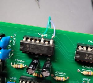
The offending pinouts
It worked! But it was still missing something. I peeked a little towards the end of the book where it talks about sound generation, and it looked so easy, I couldn’t not implement it into the design. I simply threw the circuit together on a small prototype board, and just poked around on the circuit until i found the right pin to trigger the sound circuit (pin 15 of the 74LS76, which changes depending on whether or not the squares overlap).
I put into a handsome little cigar box with some vintage new-old stock radio knobs. It looked great! But now it didn’t work. What the hell happened? I poured over the PCB, desperately searching for perhaps a cold solder joint, or maybe one of the ICs wasn’t seated correctly. I moved the pins around connecting to the sourceboard, wondering if maybe something there didn’t work. Nothing. So I desoldered the flimsy jumper wires and built a more sturdy connection using thicker, more durable wire. Same result.
I noticed though, that depending on where I handled the board, the squares would briefly reform into their expected shapes before glitching back out. My natural capacitance was evening out something. Why not just try putting it across the VCC and GND inputs? I put a little 100nf across them, and the problem was solved. The first actual game using the sourcebox was done!


Next time, we’ll see if we can get something a bit more complicated going…
